
Introduction to Object-Orientation and the UML
The prevalence of programming languages such as Java, C++, Python, and C# makes it incredibly clear that object-orientation has become the approach of choice for new development initiatives. Although procedural languages such as COBOL and PL/1 will likely be with us for decades, it is clear that most organizations now consider these environments as legacy technologies that must be maintained and ideally retired at some point. Progress marches on.
My experience is that agile software developers, be they application developers or data engineers, must minimally have an understanding of object orientation if they are to be effective. This includes understanding basic concepts such as inheritance, polymorphism, and object persistence. Furthermore, all developers should have a basic understanding of the industry-standard Unified Modeling Language (UML). A good starting point is to understand what I consider to be the core UML diagrams – use case diagrams, sequence diagrams, and class diagrams – although as I argued in An Introduction to Agile Modeling and Agile Documentation you must be willing to learn more models over time.
One of the advantages of working closely with other IT professionals is that you learn new skills from them, and the most effective object developers will learn and adapt fundamental concepts from other disciplines. An example is class normalization, the object-oriented version of data normalization, a collection of simple rules for reducing coupling and increasing cohesion within your object designs.
This article overviews the fundamental concepts and techniques that application developers use on a daily basis when working with object technology. This article is aimed at Agile data engineers that want to gain a basic understanding of the object paradigm, allowing them to understand where application developers are coming from. The primary goal of this article is to provide Agile data engineers with enough of an understanding of objects so that they have a basis from which to communicate with application developers. Similarly, other articles overview fundamental data concepts, such as relational database technology and data modeling, that application developers need to learn so that they understand where Agile data engineers are coming from.
Table of Contents
1. Object-Oriention: Concepts
Agile software developers, including Agile data engineers, need to be familiar with the basic concepts of object-orientation. The object-oriented (OO) paradigm is a development strategy based on the concept that systems should be built from a collection of reusable components called objects. Instead of separating data and functionality as is done in the structured paradigm, objects encompass both. While the object-oriented paradigm sounds similar to the structured paradigm, as you will see at this site it is actually quite different. A common mistake that many experienced developers make is to assume that they have been “doing objects” all along just because they have been applying similar software-engineering principles. To succeed you must recognize that the OO approach is different than the structured approach.
To understand OO you need to understand common object terminology. The critical terms to understand are summarized in Table 1. I present a much more detailed explanation of these terms in The Object Primer 3/e. Some of these concepts you will have seen before, and some of them you haven’t. Many OO concepts, such as encapsulation, coupling, and cohesion come from software engineering. These concepts are important because they underpin good OO design. The main point to be made here is that you do not want to deceive yourself – just because you have seen some of these concepts before, it don’t mean you were doing OO, it just means you were doing good design. While good design is a big part of object-orientation, there is still a lot more to it than that.
Table 1. A summary of common object-oriented terms.
| Term | Description |
| Abstract class | A class that does not have objects instantiated from it |
| Abstraction | The identification of the essential characteristics of an item |
| Aggregation | Represents “is part of” or “contains” relationships between two classes or components |
| Aggregation hierarchy | A set of classes that are related through aggregation |
| Association | Objects are related (associated) to other objects |
| Attribute | Something that a class knows (data/information) |
| Class | A software abstraction of similar objects, a template from which objects are created |
| Cohesion | The degree of relatedness of an encapsulated unit (such as a component or a class) |
| Collaboration | Classes work together (collaborate) to fulfill their responsibilities |
| Composition | A strong form of aggregation in which the “whole” is completely responsible for its parts and each “part” object is only associated to the one “whole” object |
| Concrete class | A class that has objects instantiated from it |
| Coupling | The degree of dependence between two items |
| Encapsulation | The grouping of related concepts into one item, such as a class or component |
| Information hiding | The restriction of external access to attributes |
| Inheritance | Represents “is a”, “is like”, and “is kind of” relationships. When class “B” inherits from class “A” it automatically has all of the attributes and operations that “A” implements (or inherits from other classes) |
| Inheritance hierarchy | A set of classes that are related through inheritance |
| Instance | An object is an instance of a class |
| Instantiate | We instantiate (create) objects from classes |
| Interface | The definition of a collection of one or more operation signatures that defines a cohesive set of behaviors |
| Message | A message is either a request for information or a request to perform an action |
| Messaging | In order to collaborate, classes send messages to each other |
| Multiple inheritance | When a class directly inherits from more than one class |
| Multiplicity | A UML concept combining the data modeling concepts of cardinality (how many) and optionality. |
| Object | A person, place, thing, event, concept, screen, or report |
| Object space | Main memory + all available storage space on the network, including persistent storage such as a relational database |
| Operation | Something a class does (similar to a function in structured programming) |
| Override | Sometimes you need to override (redefine) attributes and/or methods in subclasses |
| Pattern | A reusable solution to a common problem taking relevant forces into account |
| Persistence | The issue of how objects are permanently stored |
| Persistent object | An object that is saved to permanent storage |
| Polymorphism | Different objects can respond to the same message in different ways, enable objects to interact with one another without knowing their exact type |
| Single inheritance | When a class directly inherits from only one class |
| Stereotype | Denotes a common usage of a modeling element |
| Subclass | If class “B” inherits from class “A,” we say that “B” is a subclass of “A” |
| Superclass | If class “B” inherits from class “A,” we say that “A” is a superclass of “B” |
| Transient object | An object that is not saved to permanent storage |
It is important for Agile data engineers to understand the terms presented above because the application developers that you work with will use these terms, and many others, on a regular basis. To communicate effectively with application developers you must understand their vocabulary, and they must understand yours. Another important aspect of learning the basics of object orientation is to understand each of the diagrams of the Unified Modeling Language (UML) – you don’t need to become a UML expert, but you do need to learn the basics.
2. An Overview of The Unified Modeling Language
The goal of this section is to provide you with a basic overview of the UML, it is not to teach you the details of each individual technique. Much of the descriptiv material in this section is modified from The Elements of UML Style, a pocket-sized book that describes proven guidelines for developing high-quality and readable UML diagrams, and the examples from The Object Primer 3/e . A good starting point for learning the UML is UML Distilled as it is well written and concise. If you want a more thorough look at the UML, as well as other important models that the UML does not include, then you’ll find The Object Primer 3/e to be a better option.
It is also important to understand that you don’t need to learn all of the UML notation available to you, and believe me there’s a lot, but only the notation that you’ll use in practice. The examples presented in this section, there is one for each UML diagram, use the core UML. As you learn each diagram focus on learning the core notation first, you can learn the rest of the notation over time as you need to.
2.1 Core UML Diagrams
Let’s begin with what I consider to be the three core UML diagrams for developing business software: UML use case diagrams, UML sequence diagrams , and UML class diagrams. These are the diagrams that you will see used the most in practice – use case diagrams to overview usage requirements, sequence diagrams to analyze the use cases and map to your classes, and class diagrams to explore the structure of your object-oriented software (what I like to refer to as your object schema). These three diagrams will cover 80% of your object modeling needs when building a business application using object technology.
2.1.1 UML Use Case Diagrams
According to the UML specification a use case diagram is “a diagram that shows the relationships among actors and use cases within a system.” Use case diagrams are often used to:
- Provide an overview of all or part of the usage requirements for a system or organization in the form of an essential (Constantine and Lockwood 1999) model or a business model (Rational Corporation 2001)
- Communicate the scope of a development initiative
- Model the analysis of your usage requirements in the form of a system use case model (Cockburn 2001a)
Figure 1 depicts a simple use case diagram. This diagram depicts several use cases, actors, their associations, and optional system boundary boxes. A use case describes a sequence of actions that provide a measurable value to an actor and is drawn as a horizontal ellipse. An actor is a person, organization, or external system that plays a role in one or more interactions with your system. Actors are drawn as stick figures. Associations between actors and classes are indicated in use-case diagrams, a relationship exists whenever an actor is involved with an interaction described by a use case. Associations between actors and use cases are modeled as lines connecting them to one another, with an optional arrowhead on one end of the line indicating the direction of the initial invocation of the relationship.
Figure 1. A UML use case diagram.
Associations also exist between use cases in system use case models and are depicted using dashed lines with the UML stereotypes of <<extend>> or <<include>>, as you see in Figure 2. It is also possible to model inheritance between use cases, something that is not shown in the diagram. The rectangle around the use cases is called the system boundary box and as the name suggests it delimits the scope of your system – the use cases inside the rectangle represent the functionality that you intend to implement.
Figure 2. Associations between use cases.

Figure 3 depicts an example of a use case diagram for a university information system. This is the level of detail that you would commonly see with use case diagrams in practice. A good reference is UML use case diagram style guidelines.
Figure 3. A use case diagram for university application.

2.1.2 Object-Orientation: UML Sequence Diagrams
UML sequence diagrams are a dynamic modeling technique, as are collaboration diagrams and activity diagrams described below. UML sequence diagrams are typically used to:
- Validate and flesh out the logic of a usage scenario. A usage scenario is exactly what its name indicates – the description of a potential way that your system is used. The logic of a usage scenario may be part of a use case, perhaps an alternate course; one entire pass through a use case, such as the logic described by the basic course of action or a portion of the basic course of action plus one or more alternate scenarios; or a pass through the logic contained in several use cases, for example a student enrolls in the university then immediately enrolls in three seminars.
- Explore your design because they provide a way for you to visually step through invocation of the operations defined by your classes.
- To detect bottlenecks within an object-oriented design. By looking at what messages are being sent to an object, and by looking at roughly how long it takes to run the invoked method, you quickly get an understanding of where you need to change your design to distribute the load within your system. In fact some CASE tools even enable you to simulate this aspect of your software.
- Give you a feel for which classes in your application are going to be complex, which in turn is an indication that you may need to draw state chart diagrams for those classes.
For example Figure 4 models a portion of the basic course of action for the “Enroll in Seminar” use case. The boxes across the top of the diagram represent classifiers or their instances, typically use cases, objects, classes, or actors. Because you can send messages to both objects and classes, objects respond to messages through the invocation of an operation and classes do so through the invocation of static operations, it makes sense to include both on sequence diagrams. Because actors initiate and take an active part in usage scenarios they are also included in sequence diagrams. Objects have labels in the standard UML format “name: ClassName” where “name” is optional (objects that have not been given a name on the diagram are called anonymous objects). Classes have labels in the format “ClassName,” and actors have names in the format “Actor Name” – both common naming conventions.
Figure 4. A UML sequence diagram.

I have a tendency to hand draw sequence diagrams on whiteboards. Two such examples are show in Figure 5 and Figure 6. Figure 5 depicts a UML sequence diagram for the Enroll in University use case, taking a system-level approach where the interactions between the actors and the system are show. Similarly, Figure 6 depicts a sequence diagram for the detailed logic of a service to determine if an applicant is already a student at the university.
Figure 5. Enrolling in University.

Figure 6. Searching for student records.
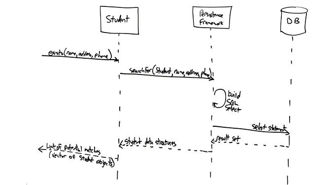
UML sequence diagramming is described in detail here, and a good style reference is UML sequence diagram style guidelines.
2.1.3 Object-Orientation: UML Class Diagrams
UML class diagrams show the classes of the system, their inter-relationships, and the operations and attributes of the classes. Class diagrams are typically used, although not all at once, to:
- Explore domain concepts in the form of a domain model
- Analyze requirements in the form of a conceptual/analysis model
- Depict the detailed design of object-oriented or object-based software
A class model is comprised of one or more class diagrams and the supporting specifications that describe model elements including classes, relationships between classes, and interfaces. Figure 3 depicts an example of an analysis UML class diagram. Classes are shown as boxes with three sections – the top for the name of the class, the middle for the attributes, and the bottom for the operations. Associations between classes are depicted as lines between classes. Associations should include multiplicity indicators at each end, for example 0..1 representing “zero or one” and 1..* representing “one or more”. Associations may have roles indicated, for example the mentors association, a recursive relation that professor objects have with other professor objects, indicates the roles of advisor and associate. A design class model would show greater detail. For example it is common to see the visibility and type of attributes depicted on design class diagrams as well as full operation signatures.
Figure 7. A UML class diagram.

A detailed description of class diagramming is provided here, and a good style reference at UML class diagram style guidelines.
2.2 Different Goals, Different Core Diagrams
What happens if you’re not developing business application development, are their different core diagrams? Yes. For real-time or embedded systems the core diagrams are typically UML state machine diagrams, UML communication diagrams (or UML sequence diagrams depending on your team’s preference), and UML class diagrams. For architecture efforts the core diagrams are often UML deployment and UML component diagrams. All of these diagrams are valuable, in the right situations. Every agile software developer should learn how to work with these diagrams at some point in their careers, but they likely aren’t the first model types that you are likely to learn.
3. Object-Orientation: Class Normalization
In the data world there is a common process called data normalization by which you organize data in such a way as to reduce and even eliminate data redundancy, effectively increasing the cohesiveness of data entities. Can the techniques of data normalization be applied to object schemas? Yes, but this isn’t an ideal approach because data normalization only deals data and not behavior. We need to consider both when normalizing our object schema. We need to rethink our approach. Class normalization is a process by which you reorganize the structure of your object schema in such a way as to increase the cohesion of classes while minimizing the coupling between them.
Fundamentally class normalization is a technique for improving the quality of your object schemas. The exact same thing can be said of the application of common design pattern, such as those defined by the “Gang of Four (GoF)” in Design Patterns (Gamma et. al. 1995) . Design patterns are known solutions to common problems, examples of which include the Strategy pattern for implementing a collection of related algorithms and the Singleton pattern for implementing a class that only has one instance. The application of common design patterns will often result in a highly normalized object schema, although the overzealous application of design patterns can result in you overbuilding your software unnecessarily. As Agile Modeling (AM) suggests, you should follow the practice Apply Patterns Gentlyand ease into a design pattern over time.
Another common approach to improving object schemas is refactoring (Fowler 1999). Refactoring is a disciplined way to restructure code by applying small changes to your code to improve its design. Refactoring enables you to evolve your design slowly over time. Class normalization and refactoring fit together quite well – as you’re normalizing your classes you will effectively be applying many known refactorings to your object schema. A fundamental difference between class normalization and refactoring is that class normalization is typically performed to your models whereas refactorings are applied to your source code.
4. What Have You Learned?
This article presented a very brief overview of object-orientation (OO). I started with a summary of common OO terms to help you to understand the fundamental vocabulary that OO developers use. The table of definitions is a good start but that’s all it is, a good start. If you truly want to understand these terms, and their implications, you’ll need to do some more reading. You will also need to roll up your sleeves and work with object technology for several years to truly understand the OO paradigm, reading isn’t enough.
The next section summarized the artifacts of the Unified Modeling Language (UML), describing each of type of UML diagram, its common usage, and provided a quick example of each one. An important thing to understand about the UML is that if you are new to it that you should start with the core diagrams that are appropriate to your situation. For business application development use case diagrams, sequence diagrams, and class diagrams are the core diagrams in my experience. Furthermore, you don’t need to learn all of the notation at first, and you may never need to learn all of it, you just need to learn the enough notation to create models that are just barely good enough for your situation. Finally, you need to recognize that this article provided a brief overview of the UML, you’ll want to read other books that present a much more detailed description if you wish to learn to apply the effectively.
The third section overviewed an object-oriented design technique called class normalization, the OO equivalent of data normalization. Although these techniques aren’t as popular as refactoring or the application of design patterns, I believe that they are important because they provide a very good bridge between the object and data paradigms. The rules of class normalization provide advice that effective object designers have been doing for years, so there is really nothing new in that respect. However, they describe basic object design techniques in a manner that data professionals such as agile data engineers can readily understand, helping to improve the communication within your teams.
My hope is that you have discovered that there is a fair bit to OO. I also hope that you recognize that there is some value in at least understanding the basic fundamentals of OO, and better yet you may even decide to gain more experience in it. Object technology is real, being used for mission-critical systems, and is here to stay. At a minimum, every IT professional needs to be familiar with it.